Process
S-Flex Coupling Selection System
The assortment system for figuring out the proper S-Flex coupling involves using the charts shown around the following pages. There are 3 components for being chosen, two flanges and 1 sleeve.
Information required prior to a coupling can be chosen:
HP and RPM of Driver or operating torque
Shaft size of Driver and Driven equipment and corresponding keyways
Application or products description
Environmental ailments (i.e. extreme temperature, corrosive ailments, room limitations)
Actions In Picking out An S-Flex Coupling
Step one: Identify the Nominal Torque in in-lb of one’s application by using the following formula:
Nominal Torque = (HP x 63025)/RPM
Step 2: Making use of the Application Services Component Chart 1 pick the support issue which most effective corresponds to your application.
Step three: Determine the Style and design Torque of your application by multiplying the Nominal Torque calculated in Step one through the Application Service Issue determined in Phase two.
Style Torque = Nominal Torque x Application Services Element
Stage four: Utilizing the Sleeve Performance Data Chart two select the sleeve material which greatest corresponds to your application.
Stage 5: Applying the S-Flex Nominal Rated Torque Chart 3 find the acceptable sleeve material column for your sleeve picked 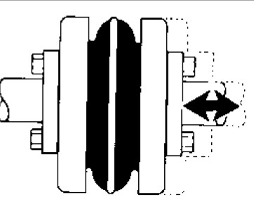 in Stage 4.
Phase six: Scan down this column towards the 1st entry exactly where the Torque Value while in the column is better than or equal to your Design and style Torque calculated in Step 3.
Refer towards the optimum RPM worth from the coupling dimension to make certain the application necessities are met. If the highest RPM value is significantly less compared to the application requirement, S-Flex couplings usually are not advisable for the application.
Note:
If Nominal Torque is significantly less than 1/4 of your coupling’s nominalrated torque, misalignment capacities are decreased by 1/2. As soon as torque worth is found, refer for the corresponding coupling dimension in the initial column of the S-Flex Nominal Rated Torque Information Chart three .
Phase seven: Review the application driver/driven shaft sizes towards the optimum bore dimension accessible within the coupling chosen. If coupling max bore will not be substantial ample to the shaft diameter, select the following largest coupling that will accommodate the driver/driven shaft diameters.
Stage eight: Using the Item Variety tables, come across the appropriate Keyway and Bore dimension essential and find the quantity.