
GEAR COUPLING
Gear couplings are torsionally rigid and are provided to two patterns â entirely versatile and flexible/rigid. A 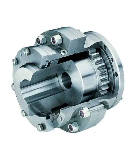 totally flexible coupling contains two hubs with an external equipment and two outer sleeves with an interior gear. It really is a common coupling for all sorts of programs and accommodates all achievable misalignments (angular, offset and mixed) as well as huge axial moments. Machines, bearings, seals, and shafts are as a result not subjected to the extra forces, at times of substantial magnitude, which come up from unavoidable misalignment normally related with rigid shaft couplings.
A adaptable/rigid coupling includes one particular adaptable geared fifty percent and a single rigid half. It does not accommodate parallel displacement of shafts but does accommodate angular misalignment. This type of couplings are largely used for “floating shaft” apps.
Dimensions 010 â 070 all have crowned enamel with a 20° pressure make contact with (fig 1). This enables to accommodate up to 1,5° static angular misalignment for every gear mesh. However, minimizing the operational misalignment will maximize the daily life of the coupling as properly as the daily life of other equipment components this kind of as bearings and so forth.
Equipment COUPLING
gear coupling is a torsionally rigid grease crammed coupling consisting of two hubs with external multicrown – and two flanged sleeves with straight internal teeth. The flanged sleeves are bolted collectively with high strength corrosion guarded fitted bolts and nuts. The sleeve is at the reverse facet of the flange executed with an endcap (interior for modest and screwed for big dimension couplings) in which the o-ring is positioned for sealing reasons. The gear coupling has been created to transmit the torque among these two flanges by way of friction keeping away from fretting corrosion amongst these faces.
The teeth of hub and sleeve are continuously in get in touch with with each other and have been made with the needed backlash to accommodate angular-, parallel- and axial misalignment in their misalignment potential. The angular and parallel misalignment capacity is established by the equipment tooth design and style and is for the regular equipment max. one.5° levels (two x .75°) in overall. The axial misalignment potential is restricted by the equipment tooth length in the sleeve and can be assorted (optionally).
Maintain browsing to learn more about CHINA GEAR COUPLING.